 English

Views: 0 Author: Site Editor Publish Time: 2026-07-31 Origin: Site


Navigating sustained mountain descents with a fully loaded vehicle introduces severe kinetic energy management challenges that standard service brakes are not designed to handle alone. Relying exclusively on friction brakes on steep grades leads to thermal degradation, commonly known as brake fade. This phenomenon exponentially increases the risk of catastrophic failure, runaway events, and accelerated maintenance cycles for fleet operators. When gravity pulls tens of thousands of pounds down a mountain, friction alone cannot safely govern the descent.
Integrating a secondary braking system—specifically a retarder—shifts the burden of speed control away from the service brakes. By utilizing hydrodynamic or electromagnetic resistance, these systems provide continuous deceleration without the destructive heat buildup associated with traditional brake pads and drums. This guide evaluates how retarders function, their operational return on investment, and how to spec them correctly for heavy-haul mountain operations.
Retarders provide continuous, fade-free deceleration, reserving the primary friction brakes for emergency stops and final halting.
Spec'ing a retarder significantly extends the lifecycle of brake pads and drums, directly reducing fleet maintenance costs and vehicle downtime.
Different retarder technologies (hydraulic vs. electromagnetic) present distinct trade-offs regarding tare weight, thermal management, and initial procurement costs.
Proper utilization requires targeted driver training—particularly regarding traction limits—as improper retarder use on slick mountain roads can induce traction loss and jackknifing.
A fully loaded tractor truck descending a 6% to 8% grade accumulates massive amounts of kinetic energy. Gravity acts as a continuous accelerant, pushing the vehicle mass downhill. To maintain a safe, controlled speed, this kinetic energy must be dissipated. Without an auxiliary braking system, the entire burden falls on the wheel-end friction brakes. Converting the kinetic energy of an 80,000-pound vehicle into thermal energy via friction generates extreme temperatures very rapidly.
Continuous friction braking generates heat that quickly exceeds the thermal capacity of standard brake drums and linings. As temperatures spike, the brake components undergo thermal expansion. The drums expand away from the brake shoes, requiring a longer stroke from the air brake pushrods to make contact. Simultaneously, the extreme heat causes the brake lining material to off-gas and glaze, creating a slick surface that drastically reduces the coefficient of friction. This cascading failure is known as brake fade, resulting in a complete loss of stopping power even when the driver applies maximum pedal pressure.
The golden rule of mountain descents dictates establishing a safe, crawl-speed baseline and selecting the appropriate gear ratio before crossing the crest of the descent. Attempting to slow down a runaway vehicle once it is already accelerating down a steep slope is a critical error. Drivers must anticipate the grade and configure the drivetrain to provide maximum resistance from the top of the hill. Gear selection locks the engine and transmission into a mechanical disadvantage against the wheels, utilizing engine compression to hold the vehicle back.
The operational baseline for safety on mountain routes is the ability to maintain a steady descent speed indefinitely without engaging the service brakes. Success is measured by the temperature of the wheel hubs at the bottom of the grade. If the service brakes remain cool, they retain 100% of their stopping power for unexpected obstacles, sharp switchbacks, or emergency stops. Achieving this baseline requires a robust auxiliary braking strategy.
| Descent Strategy | Primary Energy Dissipation | Brake Temperature Impact | Risk of Brake Fade |
|---|---|---|---|
| Service Brakes Only | Friction at wheel ends | Extreme heat buildup (>800°F) | High |
| Engine Braking Only | Engine compression | Moderate heat, localized to engine | Medium |
| Driveline Retarder | Fluid or electromagnetic drag | Minimal wheel-end heat (<200°F) | Low |
Understanding the functional distinction between wheel-end friction brakes and retarders is crucial for safe vehicle operation. Service brakes are designed to bring the vehicle to a complete stop and hold it stationary. They operate via compressed air actuating mechanical components at each wheel. Retarders, conversely, are designed strictly to govern and stabilize speed during downhill runs. They do not bring the vehicle to a halt; they provide continuous resistance against the driveline to counteract the acceleration caused by gravity.
Deceleration forces from auxiliary systems are applied at different points along the drivetrain. Systems that slow the engine itself, such as exhaust brakes or compression release brakes, apply resistance directly to the engine block. Driveline retarders apply resistance further down the power path, typically at the transmission output shaft or directly on the driveshaft. The location of the application point dictates the braking torque available and how that torque interacts with the transmission gearing.
Traditional engine compression brakes, commonly known as Jake brakes, are standard on almost every modern diesel tractor truck. They operate by altering the engine valve timing, releasing compressed air from the cylinders near top dead center. This turns the engine into an energy-absorbing air compressor. While highly effective, engine brakes have limitations regarding noise compliance. Many urban descent zones and residential areas strictly prohibit the use of unmuffled engine brakes due to their loud, staccato exhaust note. Furthermore, their maximum braking torque is generally lower than that of dedicated driveline retarders.
Modern retarders integrate seamlessly with the truck’s electronic braking system (EBS), anti-lock braking system (ABS), and cruise control. This integration enables automated downhill speed management, often referred to as Descent Mode. When the driver sets a target speed, the vehicle's computer automatically modulates the retarder stages, engine braking, and transmission gears to hold that exact speed. If the ABS detects wheel slip, the system instantly dials back the retarder torque to prevent a loss of traction, ensuring lateral stability is maintained.
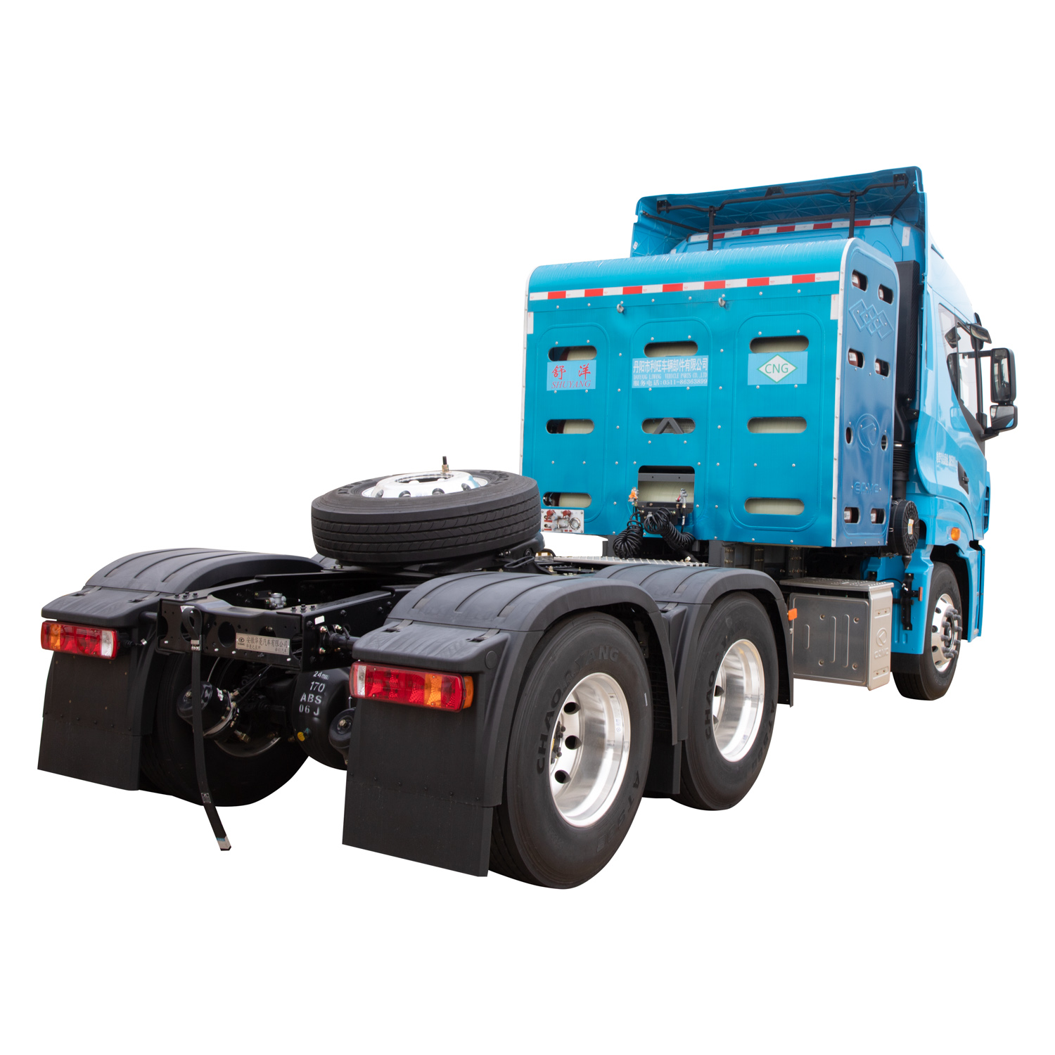
Hydraulic retarders operate on the principle of hydrodynamic drag. Fluid, typically specialized oil or engine coolant, is pumped into a chamber containing a spinning rotor attached to the transmission output shaft and a fixed stator attached to the housing. As the rotor spins, it accelerates the fluid, driving it into the stationary vanes of the stator. The stator redirects the fluid back into the rotor, creating immense fluid friction and resistance. This resistance slows the rotor, which in turn slows the transmission output shaft and the drive axles.
These systems offer exceptional braking torque, particularly at high speeds. Because the resistance is generated by fluid dynamics, the braking force increases exponentially with the rotational speed of the driveline. They integrate relatively compactly into the transmission housing of a 6x4 tractor truck, making them a popular choice for heavy-haul highway applications.
The primary trade-off is heat generation. The kinetic energy absorbed by the hydraulic retarder is converted directly into heat within the working fluid. This heat must be dissipated through the vehicle's primary engine cooling system via a heat exchanger. On long, steep descents, this can push the engine coolant temperatures near their maximum limits. Additionally, there is a slight parasitic drag on the driveline even when the retarder is disengaged, as the rotor still spins within the empty chamber.
Electromagnetic retarders utilize the principles of electromagnetic induction to create contactless, frictionless deceleration. These units consist of a series of electromagnetic coils (stators) mounted to the vehicle chassis and heavy iron rotors attached to the driveshaft. When the driver activates the retarder, electrical current flows through the stator coils, generating a powerful magnetic field. As the rotors spin through this magnetic field, eddy currents are induced within the metal. These eddy currents create their own opposing magnetic fields, generating massive resistance against the rotation of the driveshaft.
The advantages of electromagnetic systems include instantaneous response times and high effectiveness at lower speeds. Because they do not rely on fluid dynamics, they provide strong braking torque even when the vehicle is moving slowly. Crucially, they operate entirely independently of the engine cooling system. The heat generated by the eddy currents is dissipated directly into the surrounding air by the finned rotors, keeping the engine coolant temperatures stable.
However, electromagnetic retarders draw high electrical current, requiring robust alternators and heavy-duty wiring. They also add substantial unsprung weight to the chassis, often weighing significantly more than hydraulic units. Spec'ing an electromagnetic retarder requires careful consideration of driveline clearance, wheelbase length, and chassis cross-member placement to ensure proper fitment and driveshaft angles.
| Feature | Hydraulic Retarder | Electromagnetic Retarder |
|---|---|---|
| Mechanism | Hydrodynamic fluid drag (oil or water) | Electromagnetic induction (eddy currents) |
| Optimal Speed Range | Highly effective at high speeds | Effective across all speeds, including low speeds |
| Thermal Management | Relies on engine cooling system (heat exchanger) | Air-cooled directly via finned rotors |
| Weight Impact | Moderate weight addition | Heavy weight addition (unsprung mass) |
| Integration | Typically integrated into transmission housing | Mounted on the driveshaft/chassis |
Executing a safe mountain descent requires a methodical approach phase. Before the vehicle crests the hill and begins the downward slope, the driver must activate hazard lights to warn surrounding traffic of the impending slow descent. The engine or driveline retarder should be engaged, and the transmission dropped to a lower gear. The goal is to match the engine RPMs to the retarder's optimal operating range. Hydraulic retarders and engine brakes perform best at higher engine RPMs, where coolant flow is maximized and compression resistance is highest.
Assess the grade percentage and length before cresting the hill.
Reduce vehicle speed to the designated safe crawl speed.
Select a lower gear that allows the engine to run at higher RPMs without overspeeding.
Engage the retarder to the appropriate stage to hold the vehicle speed steady.
Monitor engine coolant temperatures and wheel-end brake temperatures throughout the descent.
If the descent is steeper than the retarder can handle alone, the driver must utilize the snub braking technique. Instead of lightly and continuously riding the brake pedal, the driver applies the service brakes firmly for a short duration. For example, if the safe descent speed is 35 mph, the driver allows the vehicle to reach 40 mph, then applies the brakes firmly to drag the speed down to 30 mph in a few seconds. The brakes are then released entirely, allowing the drums to cool while the vehicle slowly accelerates back to 40 mph, at which point the process is repeated.
Most modern retarders are operated via a multi-stage lever mounted on the steering column, typically offering between three and five levels of engagement. Deciphering these stages is key to smooth operation. The lower stages activate a fraction of the braking torque. These settings are ideal for minor speed adjustments in flowing traffic or for maintaining speed on light rolling hills without touching the service brakes.
The higher stages engage maximum braking torque. These levels are reserved for steep, sustained descents where aggressive speed management is required. Engaging the highest level instantly applies massive resistance to the driveline, which can be jarring if activated abruptly at high speeds.
The interface between the retarder and the transmission dictates the driving experience. With an automatic or automated manual transmission, the vehicle's computer will automatically downshift when a high retarder stage is selected. This downshift raises engine RPMs, maximizing the cooling fan speed and optimizing the retarder's efficiency. With a strictly manual transmission, the driver bears the responsibility of selecting the correct gear. If the driver selects too high a gear, the retarder will not generate sufficient torque; if they select too low a gear, the retarder's resistance combined with vehicle momentum can cause engine overspeed, potentially damaging the valvetrain.
The most critical safety outcome of utilizing a retarder is the preservation of thermal reserve in the service brakes. By delegating 80% to 90% of the deceleration workload to the retarder, the wheel-end friction brakes remain cold. This thermal reserve ensures that 100% braking efficiency is available instantaneously. Whether a deer jumps into the road, traffic suddenly halts around a blind switchback, or a sharp curve requires aggressive deceleration, cold brakes respond predictably and powerfully.
Automated descent control significantly reduces driver fatigue. Navigating complex mountain switchbacks with a heavy load is physically and mentally exhausting. Constantly monitoring speed, engine RPM, brake temperatures, and gear selection demands intense concentration. When a retarder handles the speed management autonomously, the cognitive load drops dramatically. The driver can focus entirely on steering input, lane positioning, and situational awareness, reducing the likelihood of fatigue-induced errors.
The financial impact of a retarder extends far beyond accident prevention; it fundamentally alters the maintenance schedule of the vehicle. Brake shoes and drums are consumable items, and mountain operations consume them rapidly. When a retarder absorbs the majority of the kinetic energy, the lifespan of friction components extends exponentially. Fleets often see brake replacement intervals double or triple. This directly reduces parts expenditure, labor costs, and the frequency of shop visits.
Uptime and route efficiency improve markedly. Vehicles equipped with retarders can safely maintain higher average descent speeds compared to trucks relying solely on friction brakes. Furthermore, they eliminate the need for mandatory stops at pull-outs to let smoking brakes cool down. These time savings compound over hundreds of trips, improving overall route times and maximizing fleet utilization.
Insurance providers and regulatory bodies recognize the safety benefits of auxiliary braking systems. Fleets that spec retarders on their mountain-assigned vehicles often negotiate reductions in insurance premiums. The presence of a retarder demonstrates a commitment to risk mitigation, improving compliance profiles in mountainous jurisdictions where strict brake check regulations are enforced.
The primary operational trade-off of installing a retarder is the addition of tare weight to the vehicle chassis. Hydraulic systems, including the necessary heat exchangers and fluid reservoirs, typically add between 150 and 300 pounds. Electromagnetic systems are heavier, often adding 400 to over 600 pounds depending on the required braking torque. For bulk haulers, tankers, or fleets operating near maximum gross vehicle weight limits, this added tare weight directly reduces the maximum legal payload capacity. Fleet managers must calculate whether the maintenance savings and safety benefits outweigh the revenue lost from hauling slightly less freight per trip.
Spec'ing a hydraulic retarder requires a holistic approach to the vehicle's powertrain configuration. Because hydraulic units dump massive amounts of heat into the engine coolant, the standard cooling package is often insufficient. Upgrading the engine cooling package is an absolute necessity. This involves spec'ing larger radiators with increased fin density, higher capacity water pumps, and more aggressive fan clutches. Failure to upgrade the cooling system will result in engine overheating on long descents, forcing the driver to disengage the retarder and rely on the service brakes, entirely defeating the purpose of the system.
The most severe driving risk associated with retarders is the potential for inducing a jackknife event. Driveline retarders apply massive braking torque strictly to the drive axles. If this powerful resistance is engaged on snow, ice, wet pavement, or loose gravel, it can easily overcome the available tire traction. When the drive wheels lock up or begin to slide while the steer and trailer axles continue rolling, the tractor loses lateral stability. The trailer pushes the rear of the tractor sideways, resulting in a sudden and violent jackknife.
Mitigating this risk requires strict driver training protocols. The cardinal rule of mountain driving is to disable or significantly reduce retarder levels in slick conditions. Drivers must understand that auxiliary braking is for dry pavement; slippery conditions demand the careful, balanced use of the service brakes to keep all wheels rolling at the same speed. Modern trucks integrate ABS-linked retarder cutoff switches, which automatically disable the retarder the millisecond wheel slip is detected. However, relying solely on the computer is dangerous; proactive driver intervention remains the primary defense against traction loss.
Audit your current brake replacement intervals and review the frequency of brake-related incidents on your specific mountain routes.
Consult with OEM dealers to calculate the exact payload impact versus maintenance savings of adding a retarder to your next truck order.
Implement mandatory driver training programs focused specifically on retarder operation in adverse weather conditions to prevent jackknife incidents.
Review your fleet's route topography to determine if hydraulic or electromagnetic retarders better suit your operational speed and cooling capacities.
A: No. A retarder is an auxiliary system designed strictly to manage and stabilize speed during descents. It cannot bring a vehicle to a complete halt or hold it stationary. Service brakes are always required for final stopping, emergency maneuvers, and parking.
A: An engine brake alters engine valve timing to use engine compression for resistance, often generating loud noise. A retarder applies hydrodynamic or electromagnetic resistance directly to the driveline or transmission, operating quietly and typically providing higher braking torque at speed.
A: Using a retarder on slick surfaces is highly dangerous. Because it applies braking force only to the drive axles, it can easily cause the drive wheels to lose traction on wet or icy roads, leading to a sudden loss of control and a potential jackknife.
A: The stages dictate the amount of braking torque applied. Lower stages provide mild resistance for slight speed adjustments or rolling hills. Higher stages engage maximum resistance for steep, sustained mountain descents.
A: While technically possible, retrofitting is highly complex and expensive. It requires modifying the driveshaft, upgrading the engine cooling system for hydraulic units, and integrating new electronics. It is vastly more efficient to spec a retarder from the factory.
A: A hydraulic retarder, including the necessary fluid, heat exchangers, and plumbing, typically adds between 150 and 300 pounds to the vehicle's tare weight. Electromagnetic systems are generally heavier, often exceeding 400 pounds.
A: Yes. Hydraulic retarders require regular fluid and filter changes using specific synthetic oils or coolants to handle extreme heat. Electromagnetic retarders require periodic inspections of the electrical connections, stator coils, and rotor clearances.


